
![]()

INTRODUCTION
This instruction sheet details the correct procedure for installation of your new RACING BEAT DELLORTO INDUCTION SYSTEM. While you do not need to be a mechanic to succesfully complete these instructions, you should have basic mechanical skills and a familiarity with the engine.
For your convenience your new RACING BEAT INDUCTION SYSTEM has assembled and adjusted. The following procedures are your key to enjoyment of the most powerful and responsive intake system available for your rotary engine.
IMPORTANT NOTES
1980 RX7- ALL
Disconnect the 2-wire quick disconnect (green with orange and black with red stripe) coming from the ignition 'igniter' box (near coils). This will keep the trailing ignition on all the time and prevent the leading ignition from retarding.
INSTALLATION INSTRUCTIONS
DELLORTO INTAKE KIT FOR A 1984-85 GSL-SE
1. Disconnect the battery negative terminal.
2. Remove the air pump. Remove all EGI components (except the lower intake manifold) including the fuel injection nozzles and the plastic diffusers directly below them. Remove the fuel supply and return hoses from the metal tubes on the firewall coming from the rear of the car (caution -there may be fuel pressure present in the fuel supply line - remove it slowly, and wear eye protection. Disconnect the long 3/8 I.D. hose which runs from the back of the water Pump to the area near the throttle linkage at the "throttle linkage" end disconnect the short 3/8 I.D, hose which runs from the rear housing to he throttle linkage area from the rear housing (some coolant will be lost when the choke heater hoses are disconnected).
3. Place some light oil on the O-rings installed on the injection nozzle plugs. Slip them in the intermediate housing· Use the cover plate, 2) 8mm allen bolts, (2) lock washers, and (2) flat washers to retain the plugs.
4. At the top of the engine near the oil filler neck, there are (2) black wires with round terminals which were grounded by one of the bolts holding the valve assemblies in place· Using one of the original bolts reattach these grounds.
5. Reconnect the alternator +12V lead and the quick disconnect directly to the alternator (the short extensions used on each of them are no longer necessary).
6. Remove the engine lifting eye at the top rear of the engine then reinstall the bolt and nut.
7. Find the(4)3/16" diameter rubber caps supplied in this kit. These will be installed on (4) short tubes coming out of the lower intake manifold which are left uncovered when the EGI valves were removed in step #2. Two of these caps should be installed just above the "Air Control and Check Valve" on the side of manifold nearest the right inner fender, and one should be installed very close to where the fuel injection nozzles were previously located. In addition to these (3)tubes, there is one more at the rear of the manifold near the firewall. Remove the hose which comes from the cruise control actuator from the 'T' it was connected to, and install it on the short steel tube.
8. Connect the long 3/8" diameter hose which is connected to the back of the water pump housing to the 3/8" tube extending up form the rear housing. The routing of this hose is very important, since it must clear the throttle linkage. Check for clearance at full throttle as you perform the next step.
9. Remove the tape from the outlet end of the intake manifold· Install the manifold / carburetor assembly using the gasket, (5) allen bolts, allen key supplied
10. Install the metering oil pump rod between the carburetor arm and the metering oil pump arm, using the linkage clip supplied at the top. At the bottom install one washer on the rod below the pump arm and retain it in place with the cotter pin. Bend the rod slightly to just eliminate clearance between the bottom of the pump arm and the washer. Check the throttle for smooth operation with the rod installed, then-recheck the clearance.
11. Connect the throttle cable housing to the cable bracket with the bracket between the rubber washers. It will be necessary to slip the piece of steel tubing out of the rubber insulation temporarily so that the rubber insulator can be shipped into the cable bracket. Slip the barrel shape between the throttle links closest to the throttle arm. Adjust the housing so that there is no slack in the cable, then verify full throttle
12. Slip the barrel shape on the end of the cruise control cable between the throttle links furthest from the throttle arm. Slip the cable through the slot in the cable bracket, then slip the split 6mm nut included in the kit over the cable and thread it onto the cable housing. Adjust the split nut and the nut already on the housing so that there is just a small amount of slack in the cable with the throttle at idle.
13. Remove the air control and check valve from the outside face of the lower intake manifold. Remove the three studs that attach it. Install the cover plate provided with silicon sealant. Use the (3) bolts and lock washers supplied.
14. Connect the vent hose which comes from the rear of the car to the short steel tube extending rearward from the intermediate housing below the oil filler neck. Connect the vent hose supplied from the small tube on the filler neck to the vent fitting on the air filter canister.
15. Connect the small rubber hose which supplies air to the oil metering system to fitting on the air cleaner housing.
16. Of the (2) steel tubes mounted to the firewall, the tube closest to the centerline of the car is the return line. Place the plastic cap on it. The other tube is fuel supply. Connect the 24" hose from there to the inlet fitting on the carburetor using the (2) hose clamps supplied.
17. This carburetor requires a manual choke cable. Since the "SE" RX-7 does not have a manual choke cable, we suggest obtaining one either from a carbureted RX-7 or from a Mazda dealer or Racing Beat. The control can be mounted in the standard carbureted position on the dash (below andto the left of the steering column) and the cable routed through the firewall to the carburetor.
18. In the right forward area of the engine compartment near the point where the wiring harness plugs into the air meter (below the F.I. Air filter), you will find two plastic electrical connectors. One is green, the other yellow (located inside a rubber cover). Take the short jumper wire supplied in this kit and install it on the yellow connector between two terminals in it. This will allow the fuel pumps to operate when the ignition key is turned on.
19. Reconnect the battery, and top up the cooling system.
20. Replace the fuel injection electric pump with (2) FACET electric fuel pumps connected with their fuel lines paralleled.
21. Before starting the engine, re-check throttle and choke for smooth operation and full opening/closing.
NOTE: Do not be alarmed by the hissing sound when the engine is running on the choke. This is simply the choke's air bypass circuit and indicates normal choke operation.
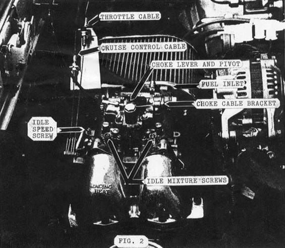
22. Once the engine is warm, idle should be 800 RPM. Idle speed is adjusted with the idle speed screw (near the throttle lever) and should be about 3 turns open from the fully closed position. The idle mixture should be adjusted by turning in each screw until the engine just peaks in RPM,then backing off the screw 1 turn. Reset idle RPM and repeat this procedure if necessary.
RECOMMENDATIONS
Ignition Advance: 1984-85 GSL-SE
Use stock advance setting
L- yellow (5° ATC) at idle
T- red (20° ATC) at idle
Vacuum advance is not used
Fuel Pumps:
(2) Facet fuel pumps (Racing Beat part# 16587)
Spark Plugs:
Nippondenso W25EDR-14
NGK BR8EQ-14
* NGK B7EV @ .020" GAP
* In 1981-85 engines a special RACING BEAT spark plug socket is necessary to install and remove these spark plugs.
Fuel Filter:
We recommend installing a FRAM G-12 in the fuel pressure line immediately upstream of the carburetor
TROUBLE SHOOTING
If you encounter a problem with the engine performance, your first step should be to re-read the instructions and verify that all procedures have been correctly completed. Should your problem persist, the following list will assist you in locating the source of trouble.
|
Problem |
Possible Cause |
|
Rough Idle |
1. Incorrectly adjusted idle mixture 2. Fuel inlet needle valve held open by foreign material 3. Idle fuel jets clogged 4. Incorrect float level |
|
High Idle |
1. Incorrectly adjusted idle speed 2. Air leak through manifold gasket |
|
Hesitation or Stumble on Acceleration |
1. Accelerator pump linkage incorrectly adjusted 2. Accelerator pump passages clogged by foreign material 3. Idle mixture to lean 4. Low float level |
|
Poor High RPM Power |
1. Low fuel pressure caused by
2. Incorrect float level |
|
Settings |
1. Float level 15mm 2. Float level 30mm 3. Accelerator pump travel 13/32" min |